When first looking at a microscope, it can sometimes be confusing if parts and controls are located in different places. However, there are always certain components that are present on a microscope. Eyepieces, objectives, and focusing controls are easy to find, but aperture and field diaphragms may not be. Field diaphragms are useful to adjust for correct microscope alignment, but are not always included in less expensive microscope models.

The aperture diaphragm (also called an iris diaphragm) controls contrast, and is found in the condenser, which sits right below the stage in line with the microscope objectives. The condenser may be movable, both in the horizontal and vertical directions. If the condenser is fixed and has no position adjustment, it has been pre-centered at the factory, but it should still have an aperture diaphragm with a movable collar or knob. There may be markings on the body of the condenser to correspond with the varying numerical apertures of the objectives used but with a bit of practice, you can make adjustments by viewing the image quality.
The collar or slider adjusts the degree the aperture is open or closed, thereby affecting the depth of field, usable numerical aperture and overall image quality. The goal of correct adjustment is a balance between the best resolution and good image contrast. If the aperture is wide open the image will appear washed out with no contrast and detail will be difficult to observe. If the diaphragm is closed down too much, the image will be "grainy" with much less resolution and addition of "artifacts" (dust and debris) into the image.
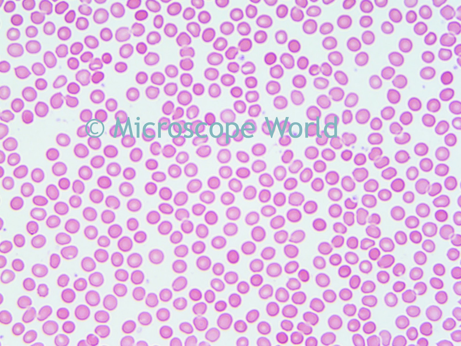
Image of tonsil tissue captured with the aperture diaphragm
open. Captured at 40x magnification with the
Swift M10 digital microscope with built-in camera.
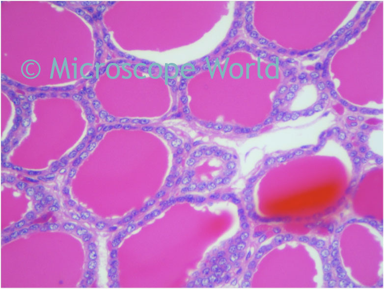
Image of tonsil tissue captured with the aperture diaphragm
correctly adjusted. Captured at 40x magnification with the
Swift M10 digital microscope with built-in camera.
Image of tonsil tissue captured with the aperture diaphragm
closed down. Captured at 40x magnification with the
Swift M10 digital microscope with built-in camera.
The aperture should be closed down approximately 1/2 to 1/3 for proper use. You can take out one of the eyepieces and look down the eyepiece tube to see the opening and closing of the aperture diaphragm while adjusting it. The more practical method of adjustment is to open the diaphragm completely and then slowly close it down while viewing the specimen. As soon as you see the contrast improve, leave the diaphragm at that setting. It is a good idea to remove one of the eyepieces and note how much the diaphragm is closed down. You will soon recognize the best position without pulling out the eyepiece.
This microscope aperture diaphragm adjustment is critical to achieve the optimal image of the sample. A poor image due to misalignment of the microscope is very noticeable and hard to explain away. Take time to work the aperture diaphragm on your microscope to optimize your image - it is time well spent.